Fire protection for unidirectional concrete slabs
Actualizado a fecha: 7 February, 2019
Many times we are refurbishing an old building using one-way forged with their beams, joists manufacted in situ or prefabricated and bollards both ceramic and lightened concrete, and at the time of justifying the resistance to the fire requested by regulation of the same we do not have enough data to ensure that they meet both the required “R” bearing capacity and the “EI” Insulation and Integrity as it is also usually an element that divides two fire sectors.
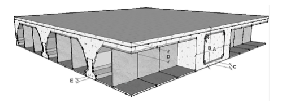
The first thing we need is to know is a series of values of the existing slab:
Being:
A and B: the dimensions of the beam,
C: the distance from the face exposed to the fire to the beam armor
D: the thickness of the compression layer
E: the distance of the face exposed to the fire to the axis of the reinforcement of the joists.
It may be that some of these values, such as the distance from the face exposed to the armor, are difficult to obtain, then we give the worst value “0”. With these values we go to DB-SI C.
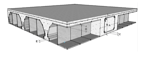
For the beam we suppose it with three faces exposed to the fire and we go to the following table:
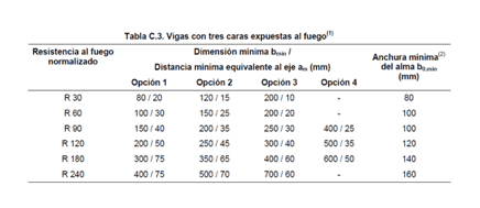
From the dimensions A / B we see which is smaller and we enter the appropriate option. For example, for a beam like the drawn one of 500 x 300 mm and an R-120 we go to option 3 and we will need a distance to the “C” armatures of 40 mm. If we fulfill perfect, we already have the capacity of the Beam Assured, if we do not know this data or it is less than required, we see the thickness of concrete that we would lack to comply with and note it
Now we are going to verify that it fulfills the rest of the wrought, there are two options
A.- If the forging meets these three conditions: The requested fire resistance is equal to or less than 120 minutes, the slabs are made of concrete or ceramics and have a lower coating (gypsum or cement). In this case, in order to verify the bearing capacity -R of the same it would be enough if the distance of the axis of the reinforcements of the joists to the face exposed to the fire complies with the second column of the following table, and the case of having to guarantee also Insulation And integrity -EI, the compression layer plus the thickness of the vault in the case of concrete and twice the thickness of the vault if it is ceramic. It would have to meet the minimum thickness of the first column of the table:
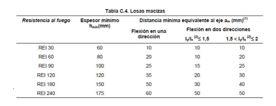
B.- When the forging does not comply with any of the three above conditions, for the purpose of the bearing capacity -R it is necessary to verify that the elements of the tunnel also meet the conditions of table C-3 above exposed for beams. For these purposes, the thickness of the wall of the concrete bollard may be computed or twice if it is a ceramic bollard, as well as any other element that is interconnected and which maintains the insulation function in the time required for the forging to be maintained. If the forge also delimits two fire sections, please comply with table C-4.
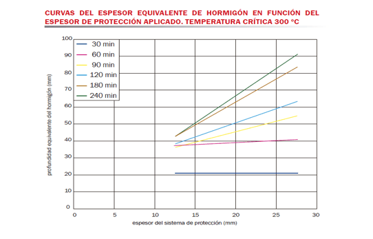
With all these values we have obtained from the DB-SI we go to our forged and see what is the most unfavorable value and what thickness of concrete we would need to solve it. The same DB-SI Annex C in its section C.2.4 speaks of Protective Layers whose contribution to the Fire Resistance of the structural element will be determined according to the standard UNE ENV 13.381-3.
From our Technical Department, solutions have been tested both with Tecbor® Panel and with Tecwool F® Mortar being more usual to perform the protection with this last product for speed of execution and economy, in addition that at the same time provides the forging of excellent acoustic insulation And thermal.
To determine the Equivalent Thickness of our protective layer we use the following graphic obtained by the test of load bearing elements and concrete delimiters according to UNE ENV 13.381-3, as it marks the CTE.
For example, if we needed extra 60 mm of concrete covering for our forging and guaranteeing a REI-120, it would be sufficient to apply 26 mm of Tecwool F mortar to the bottom of it by means of a projection.